

Gated Content Overview Headline
Lorem ipsum dolor sit amet, consectetur adipiscing elit, sed do eiusmod tempor incididunt ut labore et dolore magna aliqua.
Ut enim ad minim veniam, quis nostrud exercitation ullamco laboris nisi ut aliquip ex ea commodo consequat. Duis aute irure dolor in reprehenderit in voluptate velit esse cillum dolore eu fugiat nulla pariatur. Excepteur sint occaecat cupidatat non proident, sunt in culpa qui officia deserunt mollit anim id est laborum.
Share
Gated Content
Please fill out the form for access.
Introduction
This application note will examine the causes and cure for humidity problems in water treatment plants and pumping stations. Moisture load calculations are provided for areas with closed piping only and facilities with open tanks. The closed piping section will also pertain to pumping stations and pipe galleries.
Causes Of Humidity
Many municipalities are installing enclosures over their treatment plants to obtain better control of their process. In addition, these utilities require the installation of pumping stations (both subterranean and above ground) to facilitate the movement of water throughout the distribution system.
An ever increasing problem for the utilities is the deterioration of the treatment plant’s physical structures. Many of these problems stem from condensation on pipes, tanks, supports and electrical equipment. The moisture enters these facilities from a variety of sources:
- Infiltration and permeation
- Ventilation and make-up air
- Door and window openings
- Evaporation from open tanks
Moisture follows a physical law of nature which causes it to migrate to locations of lower concentration. This means that on hot humid summer days, moisture will find a path to the inside of a structure. This could be from poor or non-existent vapor barriers or cracks in the wall. In some instances, the outdoor air is purposely brought inside to eliminate a dangerous build-up of methane or chlorine gases. Finally, open tanks will provide a continuous source of moisture within the structure.
The moisture inside the plant will condense on any surface which has a lower dew point temperature such as the outside wall of a pipe or tank. This water will cause rust and corrosion on any of the metal surfaces. In addition, electrical controls and contacts can be affected causing extensive damage and possible process problems.

Elimination Of Moisture
Regardless of the source of moisture, the solution to the corrosion problem is simply to remove enough moisture in the space to drop the air’s dew point below that of the pipe or tank surface temperature. The following sections provide a step-by-step analysis to determine the amount of moisture removal which is required.

Refrigeration dehumidifiers reduce moisture in the air by passing the air over a cold surface, removing the moisture by condensation. A detailed discussion on this technique is explained in Desert Aire’s Technical Bulletin 1. This method is effective for desired conditions down to 45% RH for standard applications. Specially designed systems can achieve dew points as low as 39°F. This method has moderate capital costs and can recover much of the latent energy which offsets operating costs. (See Figure 2.)
Sources Of Moisture (Closed Piping)
There are many sources of moisture in a facility. A list of the common ones follows:
- Infiltration
- Permeation
- Ventilation and make-up air
- Door and window openings
- People
- Process
- Product
Moisture load in a space due to infiltration and permeation is not easily measured. Factors such as the actual moisture deviation, materials of construction, vapor barrier and room size all have an effect on the vapor migration. Desert Aire uses some basic models to make assumptions to estimate moisture infiltration and permeation.
The combined infiltration and permeation load can be approximated from the following equation:
LB/HR Moisture = V x AC x ΔGR x MF x CF / 7000 x 13.5
V = Volume of room to be conditioned (cu. ft.)
AC = Air change factor from Table 1
ΔGR = The deviation from the outdoor to the desired conditions (grains/LB)
MF = Migration factor is ΔGR / 30 (min. value = 1.0)
CF = Construction factor from Table 4
13.5 = Conversion factor for CU. FT. /LB
7000 = Conversion factor for GR/LB
According to ASHRAE, the median number of air changes per hour is 0.5. The actual number of air changes is influenced by several factors, the most dominant being the size of the room. The larger the room, the longer it takes to convert one volume. The following table compensates for the reduction in infiltration/permeation on larger or smaller volumes. THe rate of infiltration is a function of the magnitude of imbalance between the outdoor absolute humidity and that of the inside of the conditioned space. The greater the difference, the greater the driving force to make the vapor pressures equal. The migration factor compensates for this influence.
| Volume (CU. FT.) | AC | Volume | AC |
|---|---|---|---|
| Less than 10,000 | 0.65/HR. | 40,001=60,000 | 0.45 |
| 10,001-20,000 | 0.60 | 60,001-100,000 | 0.40 |
| 20,001-30,000 | 0.55 | 100,001-200,000 | 0.35 |
| 30,001-40,000 | 0.50 | OVER 200,000 | 0.30 |
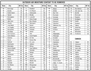
It is necessary to determine the grain differential between the outdoor condition and the “Design Condition” which is normally 5° below fluid dewpoint temperature to compensate for thermometer error, unexpected fluid temperature changes, and pipe surface temperature fluctuations. By loacting the outdoor conditions (refer to Table 2) and the design condition of the psychometric chart an absolute humidity in grains/LB can be obtained. The formula uses the difference in grains/LB between these two conditions.
Please refer to Desert Aire’s Technical Bulletin 3 if assistance is required to read the psychometric chart.

Another primary factor is the amount of moisture that is allowed to permeate through the walls, floor and roof. The construction factor takes into account the effect good vapor barriers and construction materials will have on the moisture migration. Table 4 gives factors for common construction materials. This factor will vary between 0.3 and 1.0. A composite wall must be modeled and a factor estimated.
| Description | CF Factor |
|---|---|
| Frame Construction, no vapor barrier | 1.0 |
| Masonry, no vapor barrier | 1.0 |
| Masonic, vapor proof paint | 0.75 |
| Plastic modules | 0.75 |
| Frame construction, vapor proof paint | 0.75 |
| Frame construction, mylar vapor wrap | 0.5 |
| Sheet metal, good seals | 0.3 |
| Glass | 0.3 |
Ventilation And Make-Up Air
If the facility is using outdoor make-up air for ventialation as required by some building codes, this source of air can contribute to the moisture load. This is especially important in the summer months when high humidity is common. As with the calculation for infiltration, the difference in absolute humidity must be used, along with the volume of make-up air being brought in by the air handling system.
The formlula for calculating moisture load is:
LB/HR Moisture = CFM x ΔGR x 60 / 7000 x 13.5
CFM = Volume of outdoor air introduced
ΔGR = The deviation from the outdoor to the desired conditions (grains/LB)
60 = Conversion factor for min/hr
13.5 = Conversion factor for CU.FT./LB
7000 = Conversion factor for GR/LB
Door Openings
Another source of moisture is the opening of doors and windows or other openings such as conveyor passages to the conditioned space. The amount of moisture is directly proportional to the frequency of the opening, the difference between the “Design Condition” and outdoor moisture content and the wind velocity at the opening. Wind velocity is more difficult to determine as it varies depending on the location of the opening with respect to the wind source. Local weather stations can provide details on prevailing direction and speed. A guideline is 12 CFM of outdoor air per square foot of opening. The amount of air can be estimated by the following formula. When this equation is used for a fixed opening like a window, the minutes open/hr. equals 60.
LB/HR = AREA x OPEN x ΔGR x 12 / 7000 x 13.5
AREA = Surface area of opening (sq.ft.)
OPEN – Minutes area is open per hour
ΔGR = The Deviation from the outside to the desired conditions (grains/LB)
12 = Estimated ingress of moisture (CFM/Sq.Ft.)
13.5 = Conversion factor fro CU.FT./LB
7000 = Conversion factor for GR/LB
Open Water Tanks
In the case of open water tanks, the evaporation rate can be calculated with the following equation:
LB/HR = 0.1 x AREA x (VPH20 – VPAIR)
0.1 = Factor to compensate for air movement over surface
Area = Surface area of water (square feet)
VPH20 = Vapor pressure of water at air temperature
VPAIR = Vapor pressure of air at its corresponding dew point.
*See Table #3 for Vapor Pressure.
The above equation assumes 10 to 30 FPM air velocity in room. Vapor pressures can be obtained from technical publications. Consult Desert Aire if you need assistance.
If vapor pressure of air at its corresponding dew point exceeds vapor pressure of water at water temperature, then the open water tank equation can be eliminated.
Conclusion
Properly selecting and sizing a dehumidification system to condition a facility requires careful planning. The engineer or facility operator must specify the operating conditions to be maintained and must evaluate all of the potential sources of water and the outdoor ambient conditions. This information can then be used to size the system. The enclosed worksheet is provided to organize the minumum information required for selection and sizing and the formulas will provide and approximation of the moisture load. An engineer should be consulted to confirm that the assumptions are appropriate for the application.
To select the appropriate dehumidifier, the inside ambient temperature is required. Plot the inside ambient temperature on a psychometric chart along the horizontal design dew point line. (Line C-E in Fig. 3.) This intersection will establish a dry bulb temperature and RH which can then be used to properly select a unit that provides the appropriate moisture removal capacity. If the inside ambient temperature is not known, an estimate can be made. Add 15°F to the design dew point temperature along line C-E (Fig. 3.) and proceed as described above.

Share or Download
Ask A Question
Related Products
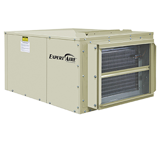
ExpertAire Wide Temperature Range (LW) Series Dehumidifier
LW Series dehumidification systems keep space humidity low while controlling outdoor air to ensure low...
View Details
Find a Desert Aire Sales Rep Near You!
Our network of independent representatives are fully trained on Desert Aire’s dehumidification and DOAS solutions and can assist you in designing and sizing your engineered solutions.