A Guide to a Controlled Environment Agriculture Chilled Water HVACD System Design

Introduction

Controlled Environment Agriculture 3 tier indoor growThis design guide will summarize the major components and options to consider when using chilled water as the source for cooling and dehumidification in heating ventilation air conditioning and dehumidification (HVACD) controlled environment agriculture (CEA) applications. There are many important design considerations that will have a significant impact on the size, capital cost, and operational cost of the system. An example will provide an overview of these impacts.

The two main solution types for integrated environmental control in CEA are direct expansion (DX) cooling and chilled water systems. In either option, there is a shared responsibility between the cultivator and the mechanical engineer to assess the facilities’ overall requirements and decide which technology best fits the needs. This guide provides a high-level overview to ensure the key points are discussed.

DX systems use a refrigerant as the energy transfer medium vs. the cold water of a chiller system. DX systems are designed for each room and are independent of the other rooms which often shifts the design complexity to the equipment manufacturer. Chillers cause more of the design responsibility to shift to a consulting engineer, but for those engineers that are experienced and/or diligent, this is not a major issue. Chiller system design is practiced by many engineers.

For nearly a decade Desert Aire has manufactured thousands of purpose-designed indoor cultivation HVACD units with a focus on optimizing energy efficiency, a high level of environmental control and overall system reliability. It all starts with a deep understanding of the air-conditioning and dehumidification loads within a grow room. When these loads are understood they can be efficiently and tightly managed with purpose-designed equipment.

Keith Coursin

President Desert Aire LLC

Keith@desert-aire.com


Direct Expansion (DX) and Chilled Water Systems Technology Direct Expansion Systems


In DX cooling air handling equipment, a refrigerant coil is placed directly in the supply air stream. As the compressed liquid refrigerant enters the evaporator (cooling coil) it evaporates and expands. As it does, the refrigerant absorbs heat lowering the temperature of the supply air stream passing through the cooling coil. In CEA applications, heat from the compression of refrigerant is used to reheat the air stream (hot gas reheat) to a temperature suitable for a grow room. Not all heating ventilation air conditioning (HVAC) systems have hot gas reheat and some only have partial hot gas reheat recovery.

DX systems can be “air-cooled packaged”, meaning the entire system is enclosed in a cabinet and is typically installed outside on a roof or on the ground next to the building. There are also “split systems” that have a part of the system installed in the building or even in the grow room itself. In these split systems, a component is installed outside to reject the energy not needed to reheat the supply air to the atmosphere.

Not all DX equipment is designed and built the same and the grower is cautioned that not all DX systems are suitable for indoor agriculture. The majority of comfort cooling (air conditioning) equipment that is designed to manage temperature and humidity for commercial applications is the DX type. Because comfort cooling equipment is not typically designed for the same level of moisture removal capacity and flexibility as process equipment built for CEA, it is not appropriate for controlling an indoor grow environment. The equipment must be capable of a wide range of dehumidification and cooling loads. During certain periods it must remove significant moisture and during other times it must remove significant heat. In technical terms, the unit must have a wide sensible heat ratio (SHR) capability. Integrated HVAC systems have additional components such as a modulating hot gas reheat coil that most air conditioners do not. This feature is extremely important to optimize energy efficiency and control.


Chilled Water Systems

2 pipe and 4 pipe chilled water system examplesChilled water systems primarily consist of the chiller plant and the air handlers. The chiller is where the refrigeration system is located and removes energy from a fluid loop. This fluid is then pumped to the air handlers where it is used to cool and dehumidify the air in the space.

Chilled water systems provide the grower with an alternative to DX systems, but similar to the DX systems, not all chilled water systems are created equally. In comfort cooling, a chilled water system can be a two-pipe system. These two pipes supply and return cold water to air handlers in the summer. In the winter the two-pipe system changes to carrying hot water to warm the building. Indoor agriculture does not have “seasons”. A two-pipe system would never work. CEA chilled water systems use four-pipe air handlers where there is a cooling coil and a heating coil. This allows for the system to match the sensible heat ratio.


Comparing Direct Expansion Systems and Chilled Water Systems


The selection of DX systems or a chiller system can be a complex choice. The chiller system can provide a greater level of control at part load in many cases. There are potential efficiency gains possible with chilled water by leveraging the scale of the chiller plant and incorporating advanced technologies that would be impractical to incorporate on a great number of individual systems through the facility. Generally, as the number of rooms in a facility increases, the centralized nature of the chiller provides greater advantages at a lower cost per square foot of conditioned space.

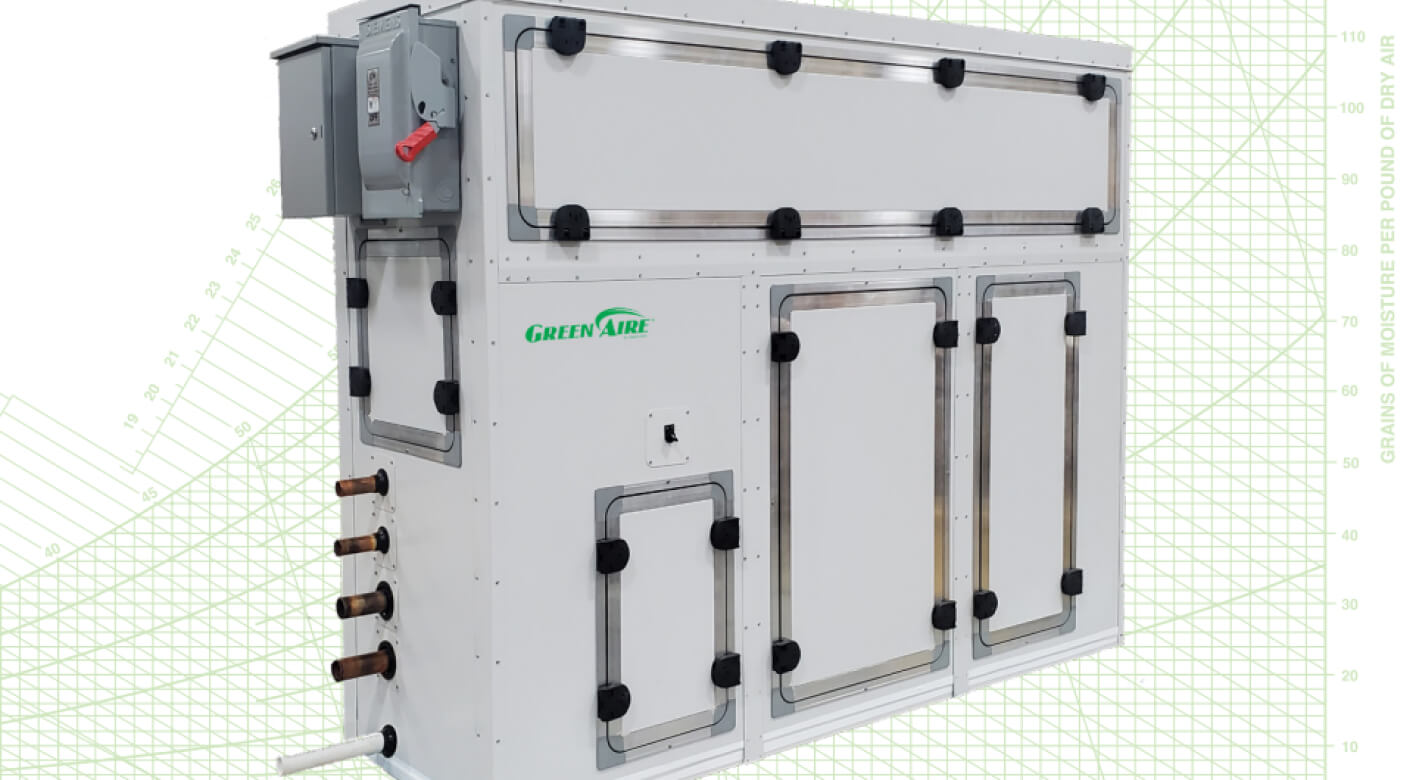
The main benefit of DX systems is reduced first cost, but the long-term maintenance and life expectancy must be reviewed carefully. An Integrated DX system’s typical median life is 10 to 15 years, whereas a chiller system’s typical mean time to replacement is 15 to 20 years. This is with the assumption of proactive preventative maintenance and service. Given the amount of time that the equipment is under load and is operational during a typical year, the centralized nature ofA chiller supplies chilled water to a Desert Aire GreenAire air handler to dehumidify a grow room the chiller plant can have significant advantages over many DX systems in a facility. This may lead to an even greater difference in the expected life of the equipment.

DX systems can use an air-side economizer, but this can create other problems (spores and insects) due to the need for a direct exchange of outside air with the space. Air-side economizers have the following limitations:

• Risk of pests is inherent with outdoor air even with filtration.

• Exhaust air required with the economizer may require odor mitigation systems.

• Control of temperature and humidity simultaneously can be difficult with air economizers. Measurement of outdoor air dew point and temperature simultaneously are required to control a minimum humidity. Complex control sequences may be involved.

• Evaluation of the number of hours beneficial per year is recommended to determine if there is an acceptable payback period for the additional cost of an air-side economizer.

A direct expansion (DX) HVACD system has advantages in CEA applicationsChillers equipped with a free-cooling option provide a simple method of using outdoor ambient conditions for energy savings without the introduction of outdoor air which may contain pests and contaminants. This is also referred to as a water-side economizer.

A water-side economizer just transfers the heat from inside to outside without exchanging airflow. This eliminates the possibility of the introduction of pests through the economizer and there is no exhaust air required for this function. The cost of the economizer still needs to be evaluated for payback, but a central system of a chiller can make the total cost of the economizer lower.

There are several other potential advantages to using chilled water systems in CEA applications:

• Chillers can provide more control over the cold coil temperature, which can enhance the independent control of temperature and humidity at all stages of plant maturity. Their performance can avoid needing humidification in early growth stages by limiting over-dehumidification.

• Potential energy savings compared to multiple individual devices providing integrated control on a room-by-room basis.

• Water piping may be simpler to run than refrigerant piping required in DX split systems. The use of water loops are likely to reduce the total piping required in a grow facility.

• Heat recovery chillers provide high overall energy efficiency and eliminate the need for a new source of energy to warm dehumidified air. The heat generated when water is chilled can be used to heat water for reheating dehumidified air.

• The centralized nature of the chiller reduces the amount of refrigerant used in a grow facility and reduces the chance for refrigerant leaks. This will help minimize the impact of the requirements associated with the new generation of A2L refrigerants (replacing the typical R410A refrigerant in 2025). These are mildly flammable refrigerants that will be required in the very near future as part of the effort to reduce global warming.

• Modular chiller capacity can be easily added as facilities are upgraded or expanded.


There are some potential disadvantages to utilizing chilled water systems in CEA applications:

• Higher initial installed cost, particularly in smaller installations

• The need to consider redundancy in the system design

• Increased sophistication of the service and maintenance staff

• The need to control corrosion, scaling, and biological contaminates in the water system

Estimating CEA Loads

For any grow room facility, it is important to calculate the individual growing room cooling, heating, and dehumidification needs. This is not a simple analysis and requires many design details such as room conditions to be defined before the task is started. Evapotranspiration calculations are interdependent on the design conditions, size of the plant canopy, type of lights used, and the impact of the building’s construction design. The chiller system must be designed for all cultivation activity, building loads, and processing requirements if post-harvesting operations are included in the facility. Refer to Desert Aire’s website (desert-aire.com) for application notes including Application Note #25: Grow Room Load Determination on the details of sizing the proper HVACD loads.

Growers with independent knowledge of the evapotranspiration rates of their crops will be prompted to provide this information to the equipment provider. Grow facilities that have rooms within a larger space or building do not have significant seasonality to their cooling and heating demands. The amount of cooling and dehumidification required is virtually the same in the summer as it is in winter. This is significantly different than traditional comfort cooling building applications which typically have to contend with heat loss or gain through walls and windows. Like cooling, the requirements for heating during the dehumidification cycle is also not seasonal.

Cultivation spaces with walls or ceilings exposed to the weather have seasonal loads that must be evaluated independently of the plant loads. The HVACD system has to have enough cooling and heating capacity to address these building envelope cooling and heating losses.

Sources for Chilled Water

A fluid chiller works by absorbing and removing the heat from the chilled water returned from the air handlers. In the air handler, air passes through the chilled water coil, cooling and dehumidifying the air. In the process, the chilled water is warmed as it absorbs energy from the air. This warmer water is carried back to the chiller to be cooled by the chiller’s refrigerant. The temperature of the chilled water must be cool enough to provide adequate dehumidification and to offset the heat loads. In general, the water must be below 42°F (7°C) to meet this requirement. Typical chilled water temperatures for indoor agriculture are 25°F to 42°F (-4°C to 7°C).

In comfort cooling applications there has been a significant emphasis on increasing the chilled water temperature wherever possible to increase the energy efficiency of the chiller. In those applications, the increase in water temperature decreases the compressor lift. This lower compressor lift creates less work for the compressor and increases the capacity and efficiency of the compressor. Higher supply water temperatures are desirable, as long as the water temperature is adequate to provide for a small amount of dehumidification.

Indoor plant grow environments have quite different requirements than comfort cooling applications. In contrast to those comfort cooling applications, supplying colder water temperatures in the indoor plant environment can actually increase the overall system efficiency. Since the need within a grow room is often dehumidification dominant, any method that increases the capacity and efficiency of moisture removal creates significant advantages.

Colder water lowers the temperature of the chilled water coil in the air handler. Just like adding more ice to a drink will result in more condensation on the glass, the lower water temperature in the air handling coil will result in more moisture condensing on the cooling coil and being removed from the air stream. The total capacity of a chiller required for a facility can then be reduced due to the improved moisture removal efficiency of the air handler. This effect is so significant that even though a given chiller will have less capacity and be less efficient at the lower water supply temperature, it is more than offset by the increased dehumidification capacity of the air handlers. The air handlers are also smaller, yet able to meet the load of the space. This reduces both capital and operational costs. There are several different types of chillers that can be utilized in CEA applications:

• Modular chillers

• Centrifugal or screw chillers

• Absorption chillers

• Natural gas chillers

These chiller options have many subcategories such as air-cooled and water-cooled. The system design engineer will select the appropriate solution for the jobsite depending on the capacity required, type of power available, the need for redundancy, and other factors. Chilled Water Source Sizing The chiller(s) should be sized for the maximum simultaneous load. This would include all of the grow rooms that will be serviced by the cooling loop (see Figure 6). This should also include the maximum design building heat gain. If the plants to be grown have a lights-on time of 12 hours or less, the chiller loop can be designed where the individual room’s lights-on modes are opposite one another, reducing the peak load and therefore the chiller size. During the lights-off period there is often still a dehumidification requirement. Therefore, this strategy can be very effective in reducing the equipment size, but the loads must still be calculated carefully to ensure adequate capacity. The grower must keep in mind that if they ever want to switch all rooms to the same light schedule that additional chiller capacity must be installed.

It should be noted that sizing equipment based on half of the rooms being in the lights-on mode and half the rooms being lights-off for 12 hour periods locks the grower into this schedule. Changing to the hours when lights are on and overlapping schedules for room operation may not be possible as the equipment capacity might not be able to handle the change.

As discussed previously, the critical criteria for sizing the chiller and air handler system is the supply water temperature. The chiller and the air handler size is directly related to the design water temperature of the loop. Lower water temperatures will reduce the capital cost because the chiller and the air handlers can be smaller. The reason the chiller can be smaller is that the air handler’s dehumidification performance increases significantly with lower water temperature, therefore the chiller can be of smaller capacity. However, lower water temperatures affect the chiller’s capacity and reduces efficiency. In general terms, the justification for slightly reduced energy efficiency of the chiller will be significantly offset by reduced size of the air handlers.

A good starting point in defining the water temperature is to consider the lowest combination of temperature and humidity that you will want during the grow cycle. In cannabis cloning, vegetative and mothering rooms, the design condition is held constant. In cannabis flowering rooms, there can be numerous design conditions defined by the cultivator. In many cases, the lights-off period or the pre-harvest condition becomes the coldest and driest condition. The chilled water supply temperature must be cold enough to dehumidify at that low condition.

Understanding Dew Point

Dew point is the temperature to which air must be cooled to become saturated with water vapor. The measurement and control to a dew point temperature is very useful in grow rooms. It is a better measurement than relative humidity (RH). Relative humidity changes with temperature even if moisture is neither added nor subtracted from the air. Dew point is a real indicator of the amount of moisture that is in the air Once the lowest room condition is known, an estimated chilled water supply temperature can be identified. The graph in Figure 2 is useful in estimating the required chilled water temperature. It can be seen that the lower the dew point required, the lower the water temperature required.

For example, a 72°F (22.2°C)/50% relative humidity (RH) room condition has a dew point temperature of 52.3°F (11.3°C). The graph indicates that the chilled water supply temperature should be designed for 40°F (4.4°C) or lower. The mechanical design engineer will need to consider other factors in selecting the final water temperature such as propylene glycol’s impact on system performance, but this is a good starting point.

Propylene glycol antifreeze may need to be added to the chilled water to prevent the potential of water freezing somewhere in the system. While propylene glycol reduces the temperature at which water will freeze, it also reduces the heat exchange effectiveness of the water. A solution of water and propylene glycol could take as much as 50% more energy to pump.

The room dew point target has a direct impact on the fluid temperature and therefore the requirement for antifreeze. A very low room dew point target can have negative impacts on capacity and efficiency. As stated previously, a lower water temperature is an advantage for dehumidification, but selecting an extremely low design dew point temperature not only increases the chiller size, but may require high concentrations of antifreeze. Since antifreeze solutions such as propylene glycol have lower heat transfer effectiveness and require larger pumps, high concentrations of antifreeze should be avoided where possible. Targeting room conditions that are approximately 50°F (10.0°C) dew point or above can avoid the need for very low chiller supply water temperatures and the propylene glycol requirement.

Chilled Water Source Redundancy

Figure 3 Waterside economizer module with separate coil for coolingHVACD operation is mission critical for any indoor growing environment. The HVACD system design should avoid a single point of failure for any critical component within the system. There are varying levels of redundancy with the cost of the components increasing if the operation cannot accept any downtime. The types of chillers to be used will also have a significant impact on the cost of redundancy.

If only one chiller is used for the entire facility, its failure would cause the entire facility to have significant issues with large crop failure. At the room level, a single air handler in a grow room would narrow the failure to only that room. If that is not acceptable, two air handlers may be used in a room. The loss of either unit would leave the grower with half the capacity. The light could be dimmed until unit repairs are completed and capacity is restored.

The grower must define the level of chiller redundancy that they are requiring for their facility. Many people are familiar with “N+1 redundancy“. N+1 means that there is a backup component in place should any single system component fail.

The ”N” in this equation stands for the number of components providing a function in the system. The ”+1” means there is one independent backup should a component of that system fail. There is also a lesser-known approach to redundancy called “N-1 scenario analysis”. The concept is simple. If the number of components providing a function is relatively high, the impact of failure in one component will be relatively low. The question to answer in controlled agriculture is how the environment for the facility or room will change if there is a single failure. There may be opportunities to reduce capital costs depending on the owner’s level of comfort with having the facility operate above the chosen conditions for periods of time due to failure.

Absorption, centrifugal, and natural gas chillers have low resiliency to a single failure. If the chiller was sized for 100% of the facilities’ load, if the chiller fails, there is no redundancy. In this case, the N+1 option would mean two chillers each sized for the entire capacity of the facility. The capital cost in the N+1 example would be very high. If you have two chillers, each sized for 50% of the facility requirements, N+1 would mean you have three units each sized for 50% of the chilled water needed. If the application required 100 tons of chilled water and the original design was a single chiller, then the N+1 would require (2) 100-ton chillers.Figure 4 Estimated annual savings with waterside economizer

If you accomplished the 100-ton load by using (2) 50-ton chillers, then the N+1 would yield (3) 50-ton chillers. The total cost of (3) 50-ton chillers would likely be less than the cost of (2) 100 chillers. Compare this to a 10-unit chiller system where a failure of one chiller would mean that temperature and humidity could be slightly above the target set point, but all the rooms would remain in the operational range. Modular chillers can often be specified with smaller compressors and more circuits. They can also be specified with redundant control systems. These strategies can lessen the impact of a single failure.

The N-1 scenario analysis should be done for each critical component in the chiller. Items that must be reviewed are:

• How many chillers are available in the case of a single failure?

• Are there multiple independent chiller units that can operate independently if there is a leak or valve failure?

• Is there a contingency in the system if the main controller fails?

• Are there redundant or backup sensors to control the system?

• Can the system continue to operate when maintenance or service is taking place?

• Create redundancy of pumps for chilled and hot water

A similar analysis should be done on the hot water side of the system and at each room.

Energy Saving Chiller Option - Water Side Economizer

“Free cooling” refers to any technique used to reduce the energy consumed by cooling systems. In colder climates, with winter design temperatures below 35°F (1.7°C), the chiller can have an extra module or component added to cool the water using the cold outdoor air. This provides cold water without the compressors having to run and using only the power of the pumps and fans. This can be achieved with a separate cooling coil or a water coil intertwined with the cooling tower condenser coil. See Figure 3 for an example.

In applications where outdoor ambient conditions are below 35ºF (2ºC), a significant energy benefit can be achieved from this free cooling function. Energy savings of approximately 2% to 11% per year can be realized with this waterside economizer function. Additionally, using the economizer rather than the refrigeration system can reduce the mechanical wear of the system. The cost to add waterside economizers (“free cooling”) will typically have a payback of less than two years for climates with more than 1,500 total hours below 35ºF (1.7ºC).

The value of savings depends on the number of hours during the year where the outside temperature is below 35ºF (1.7ºC) and the electric utility rate for the facility. The more hours that are below this level, the more savings that will be achieved.

Figure 5 shows the estimated hours below 35ºF (1.7ºC) for the U.S. and Canada. During the lights-off period of any room, there is no lighting energy to require cooling. When the air handlers are dehumidifying in the lights-off period, hot water is needed for reheat. There will be no heat available from a heat-recovery chiller when operating in the waterside economizer mode. In that case, another source of heating may be required.

Chillers in High Ambient Applications

It is recommended for jobsites with design outdoor ambient temperatures above 105°F (40°C) to use adiabatic air-cooled condensers. This assumes the water quality for an adiabatic cooler is adequate to operate and allow the appropriate condensing temperatures for the air-cooled chillers. Another option in high ambient conditions is to use a water-cooled chiller that rejects heat to a properly selected cooling tower rather than an air-cooled system.

Some parts of the country are restricting water use. Both the adiabatic cooling and cooling towers use the cooling effect of evaporating water. These options may be prohibited.

Sources for Hot Water

Reheating the supply air after the dehumidification process will be a requirement in grow rooms in order to control the humidity level and the desired temperature in the space. Using new energy for reheat, such as electric heaters, boilers, or gas furnaces, will be costly in terms of capital and operational costs. Heat recovery chillers can be selected to provide all of the hot water required for the reheat need, but not all chiller types offer this capability.

The air handler’s hot water coil must be able to provide enough energy to reheat the air in the dehumidification mode to avoid the need for an additional heater such as electric or gas. In the lights-off mode, the system should be designed to achieve leaving air temperature of at a least 5°F (2.8°C) above the target room set point. This allows for reheating the dehumidified air and offsetting the effects of evaporative cooling and space heat losses.

A heat recovery chiller removes heat from the chilled water loop and heat generated by the compressor. This recovered heat is then directed to the hot water loop. The heat energy not needed for hot water reheat is rejected to an air-cooled condenser or water loop to expel the heat to the outside air. Operation priority for the chiller is the cooling load. Heat cannot be recovered without cooling being provided. With modular chillers, it is possible to have some modules equipped with energy recovery and others without. The ratio between those that have heat recovery and those that do not should be carefully considered to ensure that the heat available at any time allows for reheat in all spaces that require reheat simultaneously. Modular heat recovery chillers are the most energy efficient method of providing chilled water, hot water and redundancy.

Heat recovery chillers will be the most energy efficient product as they create hot water from the waste heat generated from the refrigeration (cooling) process. If the selected chiller or chillers cannot provide an adequate capacity of hot water, then a backup boiler should be added.

A modular chiller system uses two or more modules to provide the system's cooling capacity. Each module is typically of smaller capacity (30 to 100 tons). When the modules work together, they create a larger capacity than one standard chiller would alone. The ability to combine several modules also assists in providing redundancy to the facility.

If sized correctly, the modular heat recovery chiller or chillers would not require additional heating equipment. Typical hot water temperatures from heat recovery chillers are 100°F to 140°F (38°C to 60°C).

If a heat recovery chiller or boiler running on waste heat is not utilized, then new energy must be used as the fuel source to create hot water. Most commercial boilers use natural gas with an efficiency range of 80% to 95%. Because of inefficiencies, the energy provided by fossil fuels is less than the energy available. Referred to as the Coefficient of Performance (COP), a value under 1.0 is not very efficient. For fossil fuel heating the COP is somewhere between .8 and .9. Compare that to heat recovery chillers that have a heating performance of 3.5 COP. For absorption chillers and boilers, hot water temperatures are typically 140°F to 180°F (60°C to 82°C).

If there are de-carbonization goals or requirements, an air to water or geothermal heat pump (see definitions below) would be needed, but this would add significant cost. The system can generate hot water by absorbing the energy from the air and creating hot water for heat. This air to water system does not work well below 40°F (4.4°C) outdoor air temperatures. Air to water heat pumps are more efficient than gas heaters if used in the correct temperature zones. A geothermal system could work, but a mechanical engineer must evaluate the soil conditions and the loads to ensure they will function correctly. Therefore, for CEA projects, the use of heat recovery chiller technology is often the lowest initial cost as well as the lowest operational cost.

Hot Water Source Sizing

Along with reheat, the capacity of the hot water heating source must consider the building construction heat loss and any other building process loads requiring additional hot water. From a dehumidification reheat perspective, we can analyze the modes using the total cooling load of the room as the basis.

• Lights-on

- When new cannabis veg plants are placed in the flower rooms, the load is dominated by the need for temperature control (sensible), and only a small amount of reheat is required (discharge cold air 60°F to 65°F).

- When plants are fully grown, the load shifts to be latent dominant, requiring discharge temperatures much closer to the room design conditions (discharge warm air 70°F to 75°F)

• Lights-off

- There is no sensible load, only a latent moisture load. The need for temperature control is supplanted by the need for humidity control. The air handlers must discharge air that is warmer than the design conditions to offset the ongoing evapotranspiration cooling (discharge air 5°F (2.8°C) warmer than the room design condition)

One of the advantages of the chiller system is the recovered heat from the chiller can be utilized in any room of the facility. From a total facility perspective there is a great diversification of plant sizes at any given time. Some plant sizes need more recovered heat to prevent the space from over cooling. The design engineer can take advantage by reducing the amount of total recovered energy required from the chiller to reduce capital expense. Hot water sizing for a CEA facility can be accomplished using the following assumptions.

• 50% to 60% of the chiller system’s total cooling capacity

- This is equivalent to 40% to 45% of the total heat of rejection

- If modular heat recovery chillers are utilized, only 50% to 60% of the units require heat recovery, the remaining can be the less expensive chiller.

• Perform a heat loss calculation of the structure and add this amount to the hot water capacity required.

Air Handler Requirements and Redundancy

An air handler is required in each room to condition the room using the chilled water and the hot water. This type of air handler is called a 4-pipe AHU (chilled water in and out and hot water in and out). Both of these water loops are required to provide independent control so that they can manage both cooling and dehumidification. Just like the chiller, it is recommended that there be more than one air handler servicing each individual grow room. While the air handlers have fewer components than the chiller or a DX unit, if one should have a failure, the additional air handler unit in the room would be able to maintain reasonable conditions for a period until repairs can be completed. A room with a single air handler fan failure would not provide any redundancy.

Desert Aire’s GreenAire™ Design

The GreenAire™ 4-pipe air handling system has the following features to control all aspects of the grow facility.

• Chilled water coil for cooling and dehumidification for temperature and humidity control

• Hot water coil for reheating dehumidified air and for heating

• Internal pump and flow control valves for precise temperature control

• Modulating fans to achieve and maintain the room set points for temperature and humidity

• Cloud-based AireGuard™ for remote control tuning by Desert Aire technicians, start-up assistance, room monitoring, room trending information, and alerts

• CO2 injection option

• Enhanced air filtration option using MERV 13 filters

The Desert Aire GreenAire™ product is a custom air handler that incorporates internal water flow control to allow the system to vary the temperature and humidity to meet the needs of the plants as they mature. The key design element is the use of Desert Aire’s special VPDsync™ control algorithm which operates on multiple dimensions to perfectly match the output of the air handler to the needs of the indoor plant environment. Those dimensions are dehumidification, cooling, airflow, water flow and water temperature.

The GreenAire™ system will determine the correct air and water flow rates along with a cooling coil temperature to match the room's need for dehumidification, cooling and heating. This provides the optimal delivered condition from the system at all times to maintain both temperature and humidity.

The GreenAire™ system will use electronically commutated motor (ECM) type fans with integral airflow rate measurement to control the amount of air delivered into the growing room. The VPDsync™ controls command the correct airflow rate for the conditions and achieve the proper fan speed regardless of air filter loading.

GreenAire™ Internal Pump

With the GreenAire™ system’s ability to vary the water temperature to the chilled water coil, the flow rate of water to the coil, and the airflow rate across the coil, the system can vary the temperature and humidity across a wide range to meet the variable demands of the grow facility. During equipment selection, the target conditions and the loads are reviewed to determine the unit operating parameters and the capacity. The goal is to maintain target humidity in the indoor plant environment while eliminating the need for standalone humidifiers and lowering energy use of the system.

One of the exclusive features of the GreenAire™ air handler is a dedicated and integral circulation pump inside the air handler. This small circulation pump is dedicated to each air handler and sized to supply chilled water into and through the air handler.  This pump reduces the main pump size by removing the internal air handler pressure drop. In addition, this dedicated air handler pump makes balancing the water flow rate much easier. It helps to ensure adequate water is flowing through each air handler.

GreenAire™ Hot Water Coil

The hot water coil has been designed with the lower water temperatures of heat recovery chillers in mind. The capacity of the coil will be sufficient to provide reheat to the air stream when more dehumidification is required so the system does not over-cool the room. In addition, the system can provide extra heat in the lights-off mode to compensate for any building heat loss. GreenAire™ chilled water air handlers can minimize the over-drying of cannabis plants during early flowering. DX HVACD systems have limitations on the range of cooling coil temperatures that are eliminated in chilled water systems. Chilled water systems can eliminate the need for humidification and its added energy costs. All humidification systems add to the capital cost and the operational cost. DX systems can be very efficient with good design, but there are limits to the accuracy without multiple compressors and extensive refrigerant system design in each and every room. Chillers provide easier tools for high turndown ratios (adjustability of system peak to minimum performance) and accurate room conditions, particularly in the lights-off period or when dehumidifier and cooling loads are low.

GreenAire™ CO2 Option 

Many grow room operators seek to supplement the carbon dioxide levels in their facilities during lights-on modes to improve the plant growth rates and qualities of crops. One of the key functions of Desert Aire’s GreenAire™ systems is to serve as the CO2 dispersion method for the controlled space. Desert Aire offers a CO2 enrichment option for its units.

The customer will supply the CO2 and connect it to the factory-provided connection port on the unit. When the CO2 levels drop below the controller-programmed set point, an internal solenoid valve will open supplying CO2 until the set point is achieved. The operation is internally coordinated with the photo-period (lights-on) command such that CO2 enrichment only occurs during the lights-on operation mode. If connected to a building automation system (BAS), the CO2 set point can be adjusted from the BAS interface. The room CO2 set point and differential are adjustable values on the Desert Aire operating controller. Desert Aire-provided CO2 sensor(s) are installed on grow room walls at plant canopy heights to measure CO2 levels at locations closest to plants. The CO2 sensor range is 0 to 5,000 ppm. A high CO2 level alert can be programmed to provide a contact closure to an audible alarm and/or visual alarm supplied by other vendors. A Life Safety CO2 Alarm/Exhaust system may be required by local officials.

Example of Supply Water Temperature and Target Conditions

The example below demonstrates the impact that room conditions and design supply water temperature can have on equipment capacity requirements. This example only considers one light type, but the analysis would be of the same proportion for HID lights at higher wattage. For simplicity of the example, the light density was kept the same for all room types.

Even at similar vapor pressure deficits (VPD), the dew point can have a large impact in the required capacity of the chiller. The following assumptions were made for this example cannabis grow facility with 8 Flower Rooms, 2 Veg Rooms and 1 Mother Room.

• Flower Rooms have 1,800 sq. ft. canopy with 40 W/sq. ft. LED lighting - Base condition at 78°F/55% RH - Low Dew Point condition at 73°F/55% RH

• Veg Rooms have 1,000 sq. ft. canopy with 40 W/sq. ft. LED lighting at 78°F/65% RH • Mother Room has 1,000 sq. ft. canopy with 40 W/sq. ft. LED lighting at 76°F/50% RH 

Impact of Target Room Dew Point

The two different flower room conditions were used in the example to compare the impact of room design conditions on system sizing of both the chiller and the air handlers. Both design conditions are at similar vapor pressure differentials, so the plant evapotranspiration rates will be similar.

The dew point of the two room design conditions (Base and Low Dew Point) is 60.6°F (15.9°C) for the Base and 55.9°F (13.3°C) for the Low Dew Point condition. This means that the air handler must cool the air in the Low Dew Point condition an additional 5°F (60.0 to 55.9°F) to reach the dew point and start to remove moisture. This requires larger air handlers (higher air volumes) and/or more air handlers to remove the required moisture. Table 2 compares the significant size difference requirement of the chiller size for this project.

Four different water temperatures were analyzed to compare the impact of unit sizing and capital cost. For an indoor installed chiller, the 45°F (7.2°C) and 42°F (5.6°C) water temperatures do not need antifreeze, but the two lower conditions may need some antifreeze added.

The lower the design water temperature the smaller the chiller capacity required. The lower water temperature makes the air handler much more effective in its moisture removal capacity, thus decreasing the overall chiller size. This reduction in size creates a significaTable 2 Total Required Chiller Capacity MBHnt reduction in the capital as well as operational costs of not only the chiller but also the air handler size.

The two lowest water temperatures require antifreeze, which due to its increase in viscosity, will require larger pumps (approximately) 50% bigger throughout the chiller and air handler components. This increases capital costs as well as pump electrical costs.

The impact of water temperature can be seen more clearly by comparing the chiller size and the system cost using the 45°F (7.2°C) water as the baseline (see Table 3). Using 32°F (0°C) water temperature at the Base flower design condition would result in a 27% reduction in chiller size and a 20% reduction in the chiller and air handler cost. The additional expense of the antifreeze and the pumping power should be analyzed.

It may be advantageous to review the minimum temperature the chiller manufacturer would recommend without antifreeze and set the supply water target at that condition while sizing the air handlers accordingly.

If the alternate Low Dew Point condition is used in the flower room a significantly larger reduction would be realized of almost half the system size and cost. Even with the increased additional cost of antifreeze and higher pumping power, Low Dew Point conditions will likely require a lower supply of water temperature to keep costs down and efficiency high (see Table 4). Table 3 Chiller size at various water temperatures (Base)

Chiller Systems Efficiency

In general, chilled water systems will be more efficient than purpose-duty DX systems that integrate temperature and humidity control. And those integrated DX systems will be more efficient than comfort cooling air conditioners and standalone dehumidifiers. The integrated, purposed-duty DX equipment will require a slightly larger capacity than a chilled water system. Comfort cooling air conditioners and standalone dehumidifiers will require even greater capacities than both chilled water and integrated DX systems.

Additionally, the chilled water systems can have better moisture removal rates than either DX system types so they use less energy. Air conditioners and standalone dehumidifier systems must run longer to remove the excess heat of the standalone dehumidifier. 

Chillers can be more efficient than DX systems in most cases. The ability of the chiller system to have many discrete compressors and variable speed compressor options allow for both good control and efficiency simultaneously. Although there are losses in exchanging the energy between the refrigerant and the water, the technology available in a large chiller can overcome this disadvantage.

To be highly efficient in the indoor plant environment, chillers must incorporate heat recovery for hot water and use waterside economizers wherever possible. Table 4 chiller size at various water temperatures Low Dew Point

Predicting Energy Use

The CEA market cannot use traditional ratings such as Integrated Part Load Values (IPLV) because the grow room internal loads are not seasonally dependent. The internal loads vary based on the stage of growth, room set points as well as the traditional solar load or heat loss. An HVACD system should have its energy efficiency rated at a few different loads to compare the best system design. Moisture removal efficiency at design conditions should be a focus rather than total capacity.

There are custom utility rebates that are available depending on the state. The use of an engineering firm familiar with the CEA market and the ability to model energy use every hour of the year would be required to determine the relative energy use at the targeted room design conditions.

The calculation of energy is a complicated analysis. Since the loads change as the plants grow, each room must be calculated separately using the following guidelines for cannabis.

• Initial Flower

Small veg plants in flower room with small latent moisture load and large sensible cooling load. Plants have very small evapotranspiration rates.

• Max Growth

Full height flowering plants at the maximum watering rate and large evapotranspiration rates

• Lights-off Period

No cooling load with lights-off and a small moisture load as evapotranspiration declines over this period. Half of the year is spent in this mode if they are operating a 12 hour lights-on and 12 hour lights-off operation.

The energy calculation must include several elements (see the System Options Energy Summary on page 16) depending on the type of chiller being used. The air handler is used in all of the rooms, but has two basic energy consumption components, fans and the chilled water circulating pump.

ConclusionFigure 10 Design conditions affect chiller equipment selection

Due to the high moisture removal need of the indoor grow room application there will be a benefit to the project by designing at lower chilled water temperatures than typical comfort cooling applications. Lower water temperatures will greatly reduce the size of the chiller by making the system capacity shift toward more dehumidification and less sensible cooling. The air handlers are also reduced in size, minimizing the capital and energy consumption. 

Chilled water systems are 15% to 20% more expensive in capital costs than a DX system. However, they can provide easier installation and deliver higher levels of control. When implementing heat recovery chillers, the ongoing energy operational costs will be lower.

The HVACD system type selection will ultimately depend on the customer's cost-benefit decisions.

The following should be discussed in detail with the client:

• Efficiency design goals

• Range of loads and set points

• Desired stability of indoor conditions

• Willingness to stagger the lighting schedule

• Ease of maintenance and service for the options

• Mean-time-to failure and system availability

Selecting mechanical systems is an exercise in making compromises, particularly when there is a budget. Many factors need to be considered to select the “best” systems for a chilled water HVAC system design. Contact us to discuss your grow project and controlled environment agriculture system design whether it is a Direct Expansion (DX) or chilled water HVACD system. We can help you decide and select the best equipment solution for your facility design and grow goals.

HVAC Definitions for the Grower

DX - Direct Expansion - the refrigerant expands to produce the cooling effect in a coil that is in direct contact with the conditioned air that will be delivered to the space.

Standalone DX Dehumidifiers - dehumidifiers with no cooling capacities and generally less than 21 lb./hr. (500 pints/day) moisture removal capacity

Integrated DX Dehumidifiers - a system that maintains both temperature and humidity and does not require other systems to meet the room requirements

Economizer - reduce air conditioning costs by using outside air (OSA) for free cooling causing the compressor to run less

Adiabatic Cooling System - remove heat by evaporating water in a stream of warm, dry air. In the process of going from a liquid to a vapor, the evaporated water simultaneously humidifies and cools the air stream to within a few degrees of the wet bulb temperature.

Adiabatic Condenser - additional water is added to pads on condenser units to precool the hot outdoor air before the refrigerant coils making them function more efficiently and with smaller coil surface areas.

Heat Pump – using a refrigeration system to transfer energy from one source to another

- Air to Water – absorbs energy from the outdoor air and transfers to a water loop

- Geothermal - absorbs energy from the earth and transfers to a water loop

HVAC Terms and Definitions

Compressor Lift - the difference in pressure between the refrigerant in the DX condenser and the refrigerant in the evaporator DX cooling coil. The higher the difference, the more work the compressor will have to do. In a chilled water system, the chilled and condenser water temperatures set the required lift.

• Sensible Load - a measurement of the amount of energy that must be removed from the air inside a grow room in order to maintain a certain temperature. It’s unit of measure is BTU/hr or kW.

Latent Load - the moisture released through the evapotranspiration process. It is normally defined in lb./hr., kg/Hr. or pints/hour.

Sensible Heat Ratio (SHR) - the term used to describe the ratio of sensible heat load to total heat load (sensible and latent).

Dew Point - the temperature the air needs to be cooled to (at constant pressure) in order to achieve a relative humidity (RH) of 100%. At this point the air cannot hold more water in the vapor form.

Vapor Pressure Deficit (VPD) - measures how much water is in the air versus the maximum amount of water vapor that could exist in that air.


Other System Components in a Chilled Water System

Air Separator - an air separator is used to remove dissolved air/gases or micro bubbles from closed or open hydronic, HVAC, boiler and other water / fluid systems. In the process it separates undissolved impurities as well.

Chemical Feeder - corrosion inhibitors and biocides are introduced into the fluid stream of a closed fluid loop. A chemical feeder introduces chemicals to the fluid to reduce pipe corrosion and biocides to control bacteria within the system. Proper closed loop water treatment can prevent the build-up of scales and corrosion that can cause damage.

Expansion Tanks - the expansion tank is designed to handle the thermal expansion of water as it heats up in the system, preventing excessive water pressure. If the water pressure gets too high, it can damage valves in plumbing fixtures, joints in supply pipes, and the water heater itself.

Glycol Feeder - this is an optional component which depends on the location of the chiller and/or the chilled water temperature. A glycol feeder can help automate the addition of fluid if there are any losses due to leakage.

Note that if any part of the system is exposed to freezing ambient conditions, then glycol is required. In addition, if the supply water temperature is approximately 38°F (3.3°C) or lower, there may be localized freezing of the water in the air handler or other parts of the system. This is especially important if the chillers use plate heat exchangers that have very small water passages. The chiller manufacturer can guide the designer through the glycol requirements of their system.

Pump(s) - the chilled water and hot water loops need a main pump or pumps to move the fluid throughout the facility. - Consider a set of pumps to provide the overall system redundancy in case of failure. Variable speed pumps can reduce the energy consumption as the system flow rate varies depending on each room's demand.


System Options Energy Summary

• Air Handler (4-pipe)

- Fan (supply air) - Internal water pump

• Air-Cooled Chiller (w/ heat recovery)

- Compressor

- Fan (air-cooled condenser)

- System chilled water pump

- System hot water pump

• Water-Cooled Chiller

- Compressor

- Condenser water pump

- Fan (cooling tower)

- System chilled water pump

- System hot water pump

• Absorption Chiller

- Heat Engine Power

- Condenser water pump

- Fan (cooling tower)

- System chilled water pump

- System hot water pump

• Waterside Economizer

- Reduction of compressor run time

- Energy savings

• Boiler

- If a heat recovery chiller is not used, estimate the energy consumed by the boiler

- Convert gas input into equivalent electrical energy and add other kW power of boiler


For more information, see Desert Aire's Grow-Related Application Notes:

AN25 Grow Room Load Determination

AN26 Grow Room Environmental Control

AN27 HVAC Systems and Grow Room Energy Usage

AN28 Vapor Pressure Deficit and HVAC System Design

AN30 Structure Design in Grow Room Applications

AN32 Natural Gas-Driven Chiller With Custom Air Handlers For Indoor Grow Facilities

AN33 Impact of Design Conditions on Grow Room Facility Performance


Headline: 
A Guide to a Controlled Environment Agriculture Chilled Water HVACD System Design